Information

Kemah, Texas
Watts Up! Marine Services has gone offshore and no longer provides local service. I have left this blog in tact for those that might find the information useful. I still monitor questions but only when internet is available.

Thanks for checking out our blog.

Thursday, January 27, 2011

NMEA 2000 - Important stuff to know

NMEA 2000, a simple and effective communication for your boat.  One concern with this communication system is...it is on a boat. 

Visualize this, you are on a boat in a shipping channel, that has a NMEA 2000 network controlling the navigation, tankage and even the engine throttle and shifting, the network goes down, you are dead in the water.  Knowing how the NMEA 2000 network is assembled suddenly becomes very important.

Every boat owner that has NMEA 2000 controlling the engine systems or relies on a NMEA 2000 navigation system, should know how the network is assembled and what it would take to troubleshoot a problem.  Taking a few hours to learn this simple system could turn around a very upsetting weekend.  They say that a "little knowledge is dangerous", I say that a whole lot of ignorance can mess your day up!  You don't have to be a "MacGyver" to get the system back up and moving in the right direction.

To learn more, visit our Tech Locker at http://www.wattsupmarine.com/

Tuesday, January 18, 2011

RCDs - How do we protect an entire circuit?

In conjunction with the previous blog posts, I wanted to answer a question that was raised; How do I protect my outlet circuits without having to change my current outlets?  Many boats have special cover plates made of teak, replacing the outlet to go to GFCI would require replacement of the cover plate and change the look of the boat.  RCDs are the solution to this problem.

Residual Current Devices (RCDs) respond to leakage of electrical current outside of the intended circuit path. When the RCD function is combined with overload and short circuit protection, the device is often referred to as an RCBO. A device that trips on leakages of nominally 5mA, and meets certain standards, is called a Ground Fault Circuit Interrupter (GFCI). A device meeting the same standards but with a trip level of 30mA is called an Electrical Leakage Circuit Interrupter (ELCI). The device to the right provides GFCI or ELCI functions and circuit protection in panel mounted breakers.  RCDs come in various sizes from 15 amp to 30 or 50 amp and can be used with 120 or 240 volt systems.  Make note, the size of the RCD can vary and the spaces that will be consumed in your electrical panel will increase with the size of the RCD.  As an example, a single circuit RCD will fill two positions in your electrical panel.

RCDs operate just like the GFCI you would find in your home or boat, they simply will protect the entire circuit to include the wiring that runs throughout your boat.  This is very important on a boat due to the flex and vibration that are an everyday occurrence, that will eventually take a toll on the the  electrical wiring.  Wire chafe is often found when removing old wiring, this chafe produced from wiring passing through bulkheads or under metal objects.  

In most cases, RCDs can replace the existing main A/C breaker (used as an ELCI), an individual circuit breaker or be added to an existing circuit depending on the existing circuitry.  It becomes an inexpensive solution that can be added to any boat.

To summarize the last couple blog posts, ELCIs will cover an entire boat, RCDs can protect an entire boat or each individual circuit and GFCIs offer protection to the individual outlet or string of outlets (if connected properly).  I hope that this sheds some light on electrical safety devices that can protect our boats and crew.

Monday, January 17, 2011

What is an ELCI? - Current protection for the entire boat!

When digging around the internet to check on any new ABYC regulations I came across some great information provided by Blue Sea Systems.  I wanted to pass this information on to anyone that is asking a question that many boaters ask; How do I detect or prevent "Stray Current"?  An ELCI, Equipment Leakage Circuit Interrupter, can do that and more.

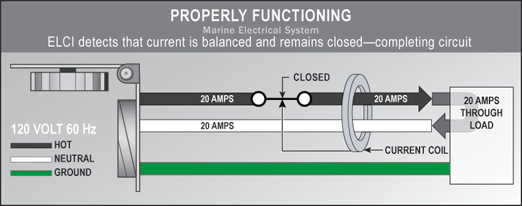
There are two potential failures in a boat′s electrical system that can put people on or around the boat at risk of lethal electric shock.  In a properly functioning marine electrical system, the same amount of AC current flows in the hot and neutral wires.

Properly Functioning Marine Electrical System
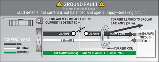
However, if electricity “leaks” from this intended path in these two wires to ground, this condition is called a ground fault. A good example of this is an insulation failure in the wiring of an appliance.
Ground Fault
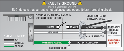
In addition, a faulty ground can occur when the grounding path is broken through a loose connection or broken wire. For instance, a shore power cord ground wire may fail due to constant motion and stress.
Faulty Ground
Faulty grounds can be undetectable; a simple continuity test will not necessarily reveal a problem.
When these two conditions occur at the same time, the results may be tragic. The combination of a ground fault and a faulty ground can result in metal parts in the boat and under water becoming energized.
In addition to the hazard to people on the vessel, there is a larger danger to swimmers near the boat. While people on board are likely to receive a shock from touching energized metal parts, nearby swimmers could receive a paralyzing dose of electricity and drown due to involuntary loss of muscle control. A Coast Guard sponsored study showed numerous instances of electrical leakage causing drowning or potential drowning even though the shock did not directly cause electrocution.
Given the seriousness of the problem, ABYC requirements now include specific measures for avoiding this danger.
ABYC regulation E–13.3.5 states:
    If installed in a head, galley, machinery space, or on a weather deck, the receptacle shall be protected by a Type A (nominal 5 milliamperes) Ground Fault Circuit Interrupter (GFCI).
ABYC regulation E–11.11.1 states:
    An Equipment Leakage Circuit Interrupter (ELCI) shall be installed with or in addition to the main shore power disconnect circuit breaker(s) or at the additional overcurrent protection as required by E11.10.2.8.3 whichever is closer to the shore power connection.
ELCIs, and the more familiar GFCIs, are part of a larger family of devices that measure current flow in the hot and neutral wires and immediately switch the electricity off if an imbalance of current flow is detected. ELCIs and GFCIs that are also Residual Current Circuit Breakers (RCBO) provide overcurrent tripping protection characteristic of a normal circuit breaker.
GFCIs are used as branch circuit ground fault protection at the 5mA threshold in potentially wet environments. GFCIs protect against flaws in devices plugged into them, but offer no protection from the danger of a failing hard-wired appliance, such as a water heater or cooktop.
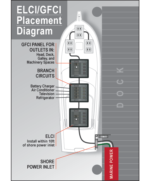
In contrast, an ELCI provides additional whole-boat protection. Installed as required within 10' of the shore power inlet, an ELCI provides 30mA ground fault protection for the entire AC shore power system beyond the ELCI. ABYC regulations still require the use of GFCIs in environments described above.
ELCI Placement
Although ABYC regulations apply only to new boat construction, the dangers and liabilities exist for any boat owner with a shore power connection. Retrofitting an ELCI to an existing AC system can be worthwhile “insurance” against risk. Since an ELCI/RCBO can serve as the main shore power circuit breaker, it can replace a standard circuit breaker in this application. Alternatively, an ELCI/RCBO can be added between the shore power inlet and the existing main shore power circuit breaker.
Safety ground system failures on boats are safety and liability disasters waiting to happen. ELCI protection on each shore power line, combined with protection afforded by GFCIs, will reduce risk to those on the boat, the dock, and in the water surrounding the boat.

GFCIs are great at protecting the devices that are plugged into them and the individuals that might be using it, they do not protect anything that is upstream on the electrical circuit.  Standard circuit breakers protect the circuit and everything downstream, yet sometimes they do not act quick enough to avoid fire or shock.  ELCI/RCBOs fill the gap that the others miss.

We hope that this information can answer some questions and make your boating experience a safer one.  Add your questions or comments if you like, we welcome the chance to discuss this valuable topic.

Friday, January 14, 2011

GFCI Danger! Something we all need to know!

In this past week, I was called out to a boat for an "electrical glitch" and found this, a little more than a glitch:
What the photo does not show is the fire and smoke that had also filled the boat.  This boat owner was extremely lucky, we were able to extinguish the fire in a matter of minutes and save the boat.  It would have otherwise surely destroyed the boat.

A Ground Fault Circuit Interrupter (GFCI) is an important part of our house and boat. It protects us against electrical shock.  A GFCI monitors the amount of current flowing from hot to neutral.  A GFCI can detect how much current is flowing to the receptacle on the "hot," or black wire, and then looks for the exact same amount flowing back on the "neutral," or white wire.  If there is any imbalance, it trips the circuit.  It is able to sense a mismatch as small as 4 or 5 milliamps, and it can react as quickly as one-thirtieth of a second.  This is great for protecting us against electrical shock, however what happens when we add saltwater or humid saltwater-rich air?  Corrosion and potential for fire.

In the photos above, the GFCI outlet was installed from the factory and installed on the vessel's exterior.  The manufacturer is a very prestigious, high-end producer of motor yachts known for building some of the best yachts in the world.  There were three outlets on the outside of the boat; each was installed in the same manner.  The manufacturer used a water-resistant cover that was spring loaded to help keep the elements out of the circuit; however, a number of errors were made in the installation.  First: they used a household approved outlet, something that can be obtained from a hardware store, NOT a marine-grade outlet.  The second is that the outlet was installed without using an electrical box.  Third, they installed this outlet exterior of the ship's cabin.  I would like to take a moment to explain each of these errors and hope to show you why these were bad decisions:
  1. Marine grade GFCI - All of the copper connections inside this device are tinned to help stop corrosion.  The household grade GFCIs will corrode, giving the potential for electrical arching.  When this arching occurs, it creates enough heat to start a fire.
  2. Electrical boxes have three functions: 1.) to prevent accidental electrical shock 2.) to keep the elements out and 3.) to minimize the amount of oxygen should a fire occur.  Without an electrical box, salt air was able to attack the GFCI and when the fire occurred, it gave the fire unlimited amounts of oxygen to allow it to expand unchecked.  If a fire occurs inside an electrical box, it will be starved for oxygen, extinguishing itself rather quickly.
  3. Using a GFCI on an external circuit is simply asking for trouble.  The elements will get to the device easier and more rapidly.  It would be better to install the GFCI in a location inside the cabin and protect the exterior outlet downstream.  By doing so, not only do you take the GFCI out of the elements but you also protect all of the wiring that goes to the outlet.
In the case above, we had contacted the manufacturer to discuss the problem and they  agreed that this is not the first case brought to their attention.  They advised us that all of the exterior GFCIs must be removed and protected from inside the ship's cabin, preferably near the electrical panel where the power begins.

I am a firm believer in GFCI circuits, they save lives!  Caution needs to be taken where they are used and how they are wired.  No boater wants to hear of this happening to any boat.  Post any of your questions here, I would be glad to answer them.

Sunday, January 9, 2011

Water Maker DIY - Part II

Today is the final post on the topic of reverse osmosis water maker systems.  In the previous post we discussed the systems needed to take water from the sea, pump it, filter it and then run it through the high pressure pump and RO membrane.  Today's topics will give more information on the things that are not usually seen: the things that keep everything running and doing what they are meant to do. 


Post RO
Automation/Controls
Automation is a convenience, but it is a convenience that I will not live without on the system that I would construct.  Yes, you could do everything manually, like changing valve positions, turning on pumps, and increasing or decreasing system pressures.  However, if you are going to have a water maker system that will last for many years to come, automation takes out some of the human error that is bound to occur.  


There are many different vendors supplying controls to run an RO water maker.  The determining factors are the amount of automation you want, the size of your water maker, the amount of power you have available and what you're willing to spend.  I am considering a Series 150 microprocessor controller made by R&D Specialties however there are numerous controllers available. Here is some information provided by HCTI:

Features:
•Economical compact package
•Liquid crystal display and multi-function keypad
•English or metric TDS and temperature values
•Visual and audible alarm, with alarm silence key
•Programmable time delays and set points
•Programmable flush mode
•Low pressure automatic reset
•NEMA 4X hinged enclosure
•Panel or frame mount
•Available with UL/CUL Listing
R&D Specialties, Series 150 RO Controller
Standard functions of the Series 150 controller are the monitoring and/or control of:
•RO high pressure pump motor
•Inlet solenoid valve
•Automatic flush solenoid valve
•Low feed pressure switch
•High pump pressure switch
•RO storage tank level switches (1 or 2)
•Permeate TDS/Conductivity
•Water temperature
•Pre-treat lockout
•Operating hours
•RO tank full override
 *TDS stands for Total Dissolved Solids 


Switch Inputs, Dry Contact:
• Pressure fault - low feed and/or high pump pressure
•Tank level high
•Tank level low
•Pickled treatment lockout
Relay Outputs:
•High pressure pump relay - 120/240V, 1 HP
•Inlet valve relay - 120/240V, 5 AMP
•Flush Valve relay - 120/240V, 5 AMP
•Relays supply same output voltage as board power (120 or 240V, VAC)


Valves/Water Control
I have seen numerous RO systems that have no automation and work very well, as long as the operator understands the system completely.  Knowing the water flow during each of the water making processes, start-up and fresh water flush can be difficult for someone that does not do this on a regular basis.   

In the system that I would design, complete automation is a requirement.  I want to be sure that anyone can operate the system even when I am not there to instruct.  Most good RO water maker controllers will have the inputs and outputs to control solenoid valves as needed.  The three way valves that will be used in this application will simply connect into the outputs on the controller.  Another function that would be handy, yet is not a must, is an automatic shut-off when the holding tanks are full.  Royce Industries makes an electronic level sensor that could be used to shut off the system when needed.  I know that I would often forget to monitor the water tank levels and it would be nice to know that the system is doing this for me.

Post Filtration
Post filtration such as carbon filters and pH neutralizers will simply help the flavor of the product water.  I feel it is a matter of preference rather than need.  In the system that I install, this will not be needed, yet could easily be installed at a later date if I so desire.  
UV Sterilizer
Ultraviolet Sterilizer
A U.V. sterilizer is recommended if the feed water (intake) is from a harbor, marina, or polluted source. The RO membrane rejects bacteria and viruses, however if biological migration occurs across the membrane, then the U.V. sterilizer will destroy 99.9 % of any biological intrusion in the product water.


Fresh Water Flush
Fresh water is required to flush or store the water maker.  Fresh water flush will greatly prolong the life of the reverse osmosis membrane elements by rinsing them with fresh water.  The fresh water flush will need to repeat itself every seven days.  By rinsing the water maker, salt water is displaced with fresh water within the RO system’s internal parts. This process will prevent corrosion of the internal parts and also reduce biological fouling of the membranes.

The fresh water used to flush the RO system is taken from the boat's pressurized fresh water system.  To ensure that chlorine does not enter the system, the pressurized water should go through a carbon filter first.  The carbon filter will remove any chlorine that might have entered the tanks when filling at the marina.
After the fresh water goes through the carbon filte,r it is a good idea to introduce it to the water maker at a “T” before or after the sediment filters.  If the fresh water is introduced before the sediment filters, it will offer additional protection to these filter cartridges.

According to one manufacturer of the RO membranes, membranes age as they sit unused. So delay the purchase of your membranes until after you finish installing the rest of the RO system and you are ready to use the system.

Pickling
The process of pickling, consists of adding a food preservative (sodium metabisulphite) to stop bacterial and fungal growth on the membranes and in the pressure vessel, is widely regarded as being effective for at least 3 months. I know of several RO systems on yachts that have been pickled for 1 year or more. One disadvantage to pickling is, the preservative leaves its mark on hoses (especially PVC), bronze fittings and stainless steel.  Given the option, I would prefer not to pickle the RO membranes but instead flush them frequently with unchlorinated fresh water.  The frequency of fresh water flush depends on ambient temperature: the warmer the temperatures, the more frequent a fresh water flush will be required.

Control automation is key to keeping the system clean and operational every time you will need it.  Many microprocessor controlled systems will give you the ability to program the frequency of fresh water flush.  Membranes can be pricy and forgetting to flush the membrane could result in added expense.  Water maker controllers can be a great insurance policy.

Ensuring that you have a properly functioning RO water system
Important things to DO: 
  1. Change the cartridge filters regularly. 
  2. Monitor the system and keep a log daily.
  3. Run the system, as much as possible, on a continuous basis.
  4. Pickle the system if you do not intend to operate for long periods.
Important things NOT to do:
  1. Permit chlorine in the feed water.
  2. Shut down the system for extended periods without pickling.
  3. Close the throttle (pressure) valve completely.
  4. Operate the system with insufficient feed flow.
  5. Allow the membrane to become dry. 
Water Temperature - How does this affect the operation?
Temperature of the feed water can affect the water maker's ability or inability to make fresh water.  As the temperature of the feed water drops, so will the fresh water production.  As the temperature of the feed water increases, the fresh water production should also increase.  With this known, a decrease in feed water temperature can be compensated by increasing the feed pressure up to the maximum allowed by the membrane, pump and associated components.  Once the maximum pressure is reached, a further decreasing temperature causes the permeate flow to decrease and nothing more can be done.  Increasing temperature is compensated by lowering the feed pressure.

Seawater/brackish water operation-What might we change?
Feed water salinity can also affect the water maker’s ability and efficiency.  An increase in the feed water salinity can be compensated by increasing the feed pressure up to the maximum. If further pressure increase is not possible, than a lowered permeate flow and system recovery has to be accepted.  A lower feed water salinity, such as the brackish bay water, allows us to decrease the feed pressure and continue to receive the same product water flow.


Budget
Now for the most important information of this series, the cost!  Currently the costs for the major components are listed below, however there are additional costs for all the minor components that I have factored into my budget.  When looking at a good water maker system, the costs will be $7,000-$10,000 for a pre-constructed system that will produce more than 100-150 gallons in a day, I think I will easily be able to do better than that.  Here are the items that will put the biggest dent in your checkbook. 
  • Low pressure feed pump     - $250
  • High pressure RO pump      - $750
  • High pressure pump motor - $250
  • High pressure vessel            - $350
  • RO membrane                      - $200
  • RO Controller                       - Awaiting pricing information
So that's it in a nutshell (in three posts!). Water makers mystify a lot of people, but they are really very simple filtration systems once you wrap your brain around exactly how they work. Questions?  Hit me. I'll be happy to answer any questions you might have about your unique situation.

Thursday, January 6, 2011

Yes, you CAN build your own water maker!

In my previous water maker posts, I described the process of installing a Sea Recovery water maker and briefly covered the components that make things work in this self-contained system. 
I want to make my own reverse osmosis (RO) system that would use components that could be found anywhere I might be cruising.  Most of the major parts of a system can be found at most local distributors or on the internet.  The challenge would be automating an off-the-shelf system. But if you understand the system and what it would require to operate, the cost savings you experience building your own water maker versus purchasing one might be worth it. 
An additional advantage is the ability to make a fully modular system.  On the sailboat that we own, our system has to be modular – we need to put each component in strategic areas to best use the available space.  Modularity also allows us to mount the high pressure pump and motor in a location that might be easier on our ears.
Let’s explore the information you need to take the plunge:

Reverse Osmosis 101
As I touched on in my previous post, RO is a separation process that uses high pressure to force a solvent through a membrane that retains the solute (solids, salt and impurities) on one side and allows the pure solvent (fresh, drinkable water) to pass to the other side.  In reverse osmosis, the idea is to use the membrane as an extremely fine filter to create drinkable water from salty water.


The membranes used for reverse osmosis have a dense barrier layer in the polymer matrix where most separation occurs. In most cases, the membrane is designed to allow only water to pass through this dense layer while preventing the passage of solutes (such as salt ions). This process requires that a high pressure be exerted on the high concentration side of the membrane, usually 30-250 psi for fresh and brackish water, and 600-1000 psi for seawater.  Most water makers designed for yachts currently operate at around 820 psi.
RO is used to reduce dissolved solids from feed waters. Municipalities and industrial facilities use RO permeate as a consistently pure drinking water supply and to transform drinking water to high purity water for industrial use at microelectronics, food and beverage, power, pharmaceutical facilities, and can be used for removing bacteria and organic contaminants.  In the production of bottled mineral water, the water passes through a RO water processor to remove pollutants and microorganisms, including the some of the smallest microbes known as Achaea

Here is a further cut away diagram to help describe the RO membrane function:

In this diagram, the "Feed" is the high pressure output from the pump and the "Back feed" is the pressure that is built up behind the pressure adjustment valve that is installed in the brine outlet line.  This high pressure then allows the "Permeate" or fresh water to filter through the membrane while leaving the impurities to continue their flow to the brine outlet.   

Looking at the complete system:
There are many components that make the RO system work. Many are very simple items and easily found.  The rough diagram below shows the water flow through the system.
Water maker diagram

To make things easier, I will break these down into three categories, Pre-RO, RO and Post-RO (Before, During and After) and list each item in the sequence that they will be used.

Pre-RO Systems
Raw Water Supply Pump – drawing sea water into the system
In the system I want to build, the seawater will enter from the raw water thru-hull and go to the supply pump.  Be sure to include a seawater strainer just after the thru-hull, thus catching any debris that might damage the pump.  This pump will deliver an adequate amount of raw water to the system and maintain 45 psi pressure to the water maker.  This pump could be 12vdc, 24vdc, 115vac or 230vac depending on the type of system you would like to use on your boat.  In my case, I would use a commercial duty 12vdc rubber impeller pump because I would like to use it for multiple purposes:
  • I will add a three-way valve before the pump, it could serve as an emergency bilge pump 
  • I will put a three-way valve after the pump to use as a saltwater wash-down pump.   
Just following the pump, I will add a pressure switch that will control the pump and system pressure to the desired feed pressure.  A pressure sending unit will also alert the RO controller to a low feed pressure status and shut down the system for safety.
Jabsco pump
 
  Sediment Filters – the initial filtration
As the RO membrane is very sensitive, it’s important to filter out larger particles before the raw water is forced through the membrane. Therefore, the raw water pump will deliver the saltwater to a series of sediment filters.  I will use common cartridge water filters, the first filtering to 30 microns and the second to 5 microns.  These filters can be purchased online or at a supply store such as Grainger.

For convenience, I would add some simple pressure gauges before and after each filter housing so that I can compare the inlet and outlet pressures.  The comparison of each pressure will tell me if the filter element is starting to become clogged.
Sediment filters

Oil Separator – keeping petroleum out of the system
Petroleum is harmful to the RO membrane, so it’s extremely important to remove any petroleum products such as diesel, oil or gasoline from the raw water before it enters the water maker system (believe me, any water, anywhere, is full of petroleum).  Petroleum will destroy the RO membrane.
Oil/Water separation filter

RO Systems – the magic that turns salt water into fresh water.
High Pressure Pump/Motor
This pump/motor combination will supply the high pressure needed to "press" the water solution through the RO membrane.  The power needed to drive the high pressure pump is higher than most marine applications, so think carefully about how your boat is able to power it – either via DC or AC.  Most 12vdc high pressure pumps require about 26 amps to operate; 24vdc would need 13 amps.  This would require most boaters to run the engine while fresh water is being produced.  If a generator is available, the choice is simple, and AC is more practical. 
There are numerous pump/motor combinations that you can find by simply conducting a quick internet search.  I have researched a number of high pressure pumps and have chosen a direct drive Cat Pump model 2SF with a Baldor motor.  This pump should deliver 0.17 gallons per minute (GPM) or 10 gallons per hour (GPH), meaning I would have to run my system for one hour each day to produce the fresh water that I usually consume.  If I increase the pump size, I could produce more water in a shorter amount of time; it all comes down to power consumption and run time.  Soundproofing this component would be a serious consideration due to the noise that it can produce.
High Pressure Cat Pump

High Pressure Vessel – the home for your RO membrane
The high pressure pump feeds seawater to the high pressure vessel, which houses the RO membrane.  This vessel has three connections or ports: one inlet and two outlets.  As the seawater passes through the vessel through the inlet port, the membrane will then separate the fresh water and the remaining brine.  The fresh water will exit at the product water port (outlet 1) and the brine will be discharged overboard via the brine port (outlet 2).  

There will be a high pressure adjustment valve on the brine outlet (outlet 2), maintaining the correct system pressure needed to force the fresh water through the membrane.  A flow meter on both the brine outlet and the product water outlet will allow you to get a good comparison of flows.  This comparison will tell you how well the system is working and if the membrane is getting fouled.

I am selecting a high-pressure vessel from HCTI from California.  Select a vessel that will offer the correct flow and dimensions that allow generic RO membranes to be used.  Common diameters are 2.5", 4" and 8" while lengths come in 14", 21" and 40".  For most recreational boaters, one RO membrane will provide all the water they might need, provided the correct sizing has been met; however, vessel/membranes can be arranged in serial or parallel to produce more product water per day.
High Pressure Vessel

RO Membrane – the diva of your water maker system
The RO membrane is the key to a water maker’s success. It is also the item that needs the most attention before building your unit, during operation and maintenance after use. 
It’s important to choose a membrane size that gives the quantity of product water you need, and to fit inside the installed high-pressure vessel.  But as with all things on a boat, bigger means pricier - replacement membranes aren’t cheap.

RO Membranes
 
I repeat: membranes aren’t cheap. So here are some tips on maintaining the longevity and integrity of this component – before, during and after use:
  • Usually, the first hour of product water from a new membrane must be discarded 
  • Keep system pressures below maximum pressures, usually 1000 psi.
  • Hydraulic shock can destroy the membrane. Slow changes in pressure must be gradually increased over a 30- 60-second time frame.  Control automation can mitigate this risk.
  • Once water is added to the membrane, it must remain moist at all times. This means you have to use the water maker regularly, or pickle it (see last bullet).
  • Avoid any sudden pressure changes to the high pressure vessel
  • Fresh water flush is crucial to longevity of the membrane.  Pickling with chemical is needed for long periods without use.
I could go on and on about this topic however there is just not enough time in the day for me to continue writing and most likely for you to continue reading.  If you made it this far, congratulations!  Join me in the next blog post when I will be discussing
  • Automation/Controls - the stuff that makes all the kids play nice together.
  • Valves/Water Control
  • Fresh Water Flush/Pickling
The RO system that is made "Do-it-yourself" style, can easily surpass the packaged systems that are currently sold.  Not only will you leave some money in your pocket but you will gain the knowledge to fix it yourself when the need presents itself.